The transition toward high-precision metal forming has forced a re-evaluation of traditional roll forming methodologies, particularly in the production of complex profiles. In the current metallurgical equipment landscape, the demand for seamless integration between forming and cutting has led to the rise of specialized solutions like comflor china, where throughput and dimensional stability are paramount.
The primary technical hurdle in modern production lines is the "stop-and-go" inefficiency of traditional shearing systems, which creates mechanical stress and reduces the lifespan of the rollers. This bottleneck affects not only the output speed but also the surface finish of the GI (Galvanized Iron) materials, necessitating a shift toward servo-controlled, non-stop cutting mechanisms to maintain structural integrity at higher velocities.
This technical analysis examines the engineering architecture of modern roll forming systems, focusing on how servo-tracking and specialized metallurgy improve production yields. We will explore the critical specifications required for high-stability output and how these components integrate into a cohesive industrial workflow via the comflor china framework.


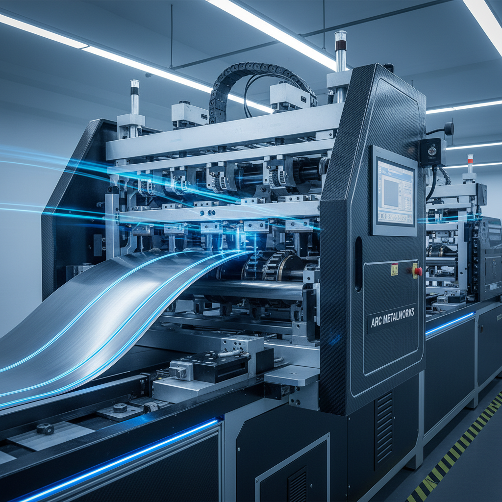
The core of the modern roll forming line is the transition from mechanical indexing to servo-driven tracking. By implementing a no-stop cutting system, the material moves continuously at speeds up to 40 meters per minute, with the cutting head synchronizing its velocity to match the strip speed. This eliminates the impact force associated with sudden deceleration, which is critical for maintaining the precision of the profile.
From an engineering perspective, this requires a high-response PLC (Programmable Logic Controller) and a touching screen interface to calibrate the timing between the forming stations and the hydraulic shear. The integration of a K-series reducer allows the system to handle varying motor powers while maintaining low noise and high torque, ensuring the long-term structural stability of the frame.
Material selection directly dictates the lifespan of the forming rollers and the final quality of the product. For the comflor china standard, Galvanized Iron (GI) with a thickness range of 0.3mm to 0.8mm is typically utilized. Operating within this thin-gauge window requires precise roller gap adjustments to prevent material stretching or "oil-canning" effects during the 10-12 forming steps.
The shafting system utilizes #45 steel with a 50mm diameter, providing the necessary rigidity to resist deflection under the pressure of the forming process. If the shaft deflects even by a fraction of a millimeter, the effective width of the profile will deviate from the drawing, leading to assembly failures in the downstream construction phase.
Furthermore, the synchronization of the 3-ton manual decoiler with the feeding guide system ensures that the material enters the first forming stand without skewing. This alignment is the first line of defense against edge waviness, ensuring that the high-speed output remains stable across the entire length of the roll.
The durability of a roll forming machine is measured by the wear resistance of its rollers. To achieve industrial-grade longevity, Cr12 tool steel is employed for both the forming rollers and the hydraulic cutting system. The material undergoes rigorous heat treatment to reach a hardness of 58-62 HRC, providing a surface that can withstand constant friction against GI sheets.
In addition to the metallurgy, the iron casting used for the wall panels ensures that the machine body absorbs vibration. When operating at 40m/min, harmonic vibrations can induce micro-oscillations in the product; the combination of cast-iron stability and Cr12 hardness effectively dampens these forces, ensuring a high-stability finish.
Evaluating the performance of a roll forming line requires a look at the relationship between forming speed and precision. In a servo-controlled environment, the "No-Stop" capability allows for a linear increase in throughput without a proportional increase in material waste. The system's efficiency is governed by the precision of the servo moving cut, which calculates the exact position of the shear in real-time.
When comparing different configuration levels, the impact of the PLC control system becomes evident. Automated tracking reduces the operator's manual intervention by nearly 90%, shifting the focus from constant adjustment to high-level system monitoring. The following assessment represents a normalized engineering rating of system performance across different operational factors.
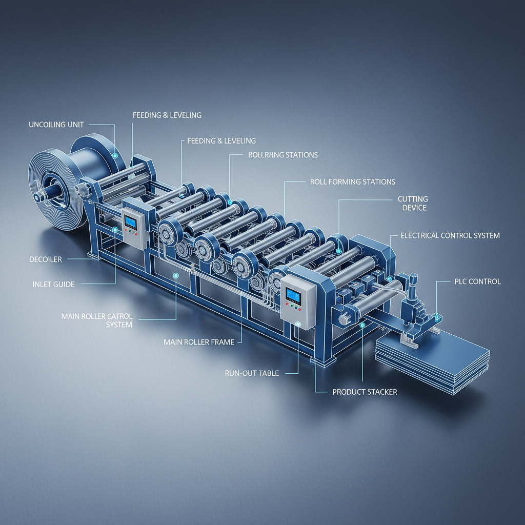
In a typical industrial deployment, the roll forming machine serves as the central node of a larger metal processing ecosystem. The workflow begins with the manual decoiler feeding the GI coil into the guide system, which maintains the strip's parallelism. As the material passes through the 10-12 forming stages, the servo-controlled cutter calculates the precise length based on the PLC input, ensuring that the resulting profiles are cut to length with minimal waste.
For operators, the primary focus during deployment is the synchronization of the 5.5kw main power system with the 2.2kw cutting power. Balancing these loads is essential to prevent voltage drops that could affect the servo tracking accuracy. Proper integration also involves the collection table, which must be ergonomically positioned to handle the high-speed output of 40m/min without creating a bottleneck in the material handling phase.
The future of roll forming is moving toward fully autonomous "Smart Factories," where IoT sensors are embedded directly into the forming rollers. These sensors can detect wear in the Cr12 steel in real-time, allowing for predictive maintenance instead of scheduled downtime. This shift will further reduce the total cost of ownership for high-output lines like those used in comflor china applications.
Another significant trend is the move toward multi-material compatibility. While GI remains the standard, there is increasing pressure to process high-strength alloys and composite-coated steels. This requires a redesign of the forming steps and an increase in the shaft diameter beyond 50mm to handle the higher forming pressures without sacrificing the 40m/min speed.
Finally, energy efficiency is becoming a primary procurement criterion. The integration of regenerative braking in the servo systems and the optimization of the hydraulic cutting cycle are reducing the carbon footprint of metal processing. Engineering teams are now prioritizing the power-to-output ratio, ensuring that the 5.5kw main motor is utilized at its peak efficiency curve.
Selecting the right configuration depends on the required output volume and the specific tolerances of the final profile. For basic utility profiles, a standard configuration with chain-driven forming is sufficient. However, for precision engineering projects, a high-duty configuration with enhanced servo tracking and reinforced iron casting is mandatory.
The decision matrix often revolves around the trade-off between initial capital expenditure and long-term operational efficiency. While an automated configuration requires a higher upfront investment in PLC and servo hardware, the reduction in labor costs and material scrap usually results in a faster ROI for large-scale manufacturers.
The following table provides an evaluation framework for different configuration profiles, allowing buyers to match their production needs with the appropriate technical capability.
| Configuration Type | Cutting Mechanism | Drive System | Recommended Use Case |
|---|---|---|---|
| Basic Configuration | Manual/Stop-Cut | Standard Chain | Low-Volume Prototype |
| Standard Configuration | Hydraulic Stop-Cut | Chain Driven | General Industrial Use |
| Precision Configuration | Servo Tracking | Precision Chain | High-Tolerence Profiles |
| High-Duty Configuration | No-Stop Servo | Reinforced Drive | 24/7 Mass Production |
| Automated Configuration | Full PLC Sync | High-Torque Servo | Smart Factory Integration |
| Industry Baseline | Standard Hydraulic | Mechanical Gear | Standard Market Entry |
No-stop cutting, powered by servo control, allows the material to move at a constant speed (up to 40m/min) while the cutter moves in synchronization with the strip. This eliminates the mechanical shock of stopping and starting the line, which significantly reduces wear on the rollers and prevents dimensional distortions in the profile, leading to higher precision and increased throughput.
Cr12 is a high-carbon, high-chromium tool steel that provides exceptional abrasion resistance. When heat-treated to 58-62 HRC, it creates a hard surface capable of forming GI sheets without rapid wear. This ensures that the profile dimensions remain stable over long production runs, reducing the need for frequent recalibration or roller replacement.
The PLC (Programmable Logic Controller) acts as the brain of the system, managing the synchronization between the decoiler, the forming stands, and the servo cutter. The touching screen allows operators to input precise length requirements and monitor real-time speed, reducing manual errors and allowing for rapid changeovers between different product specifications.
The system is engineered for thin-gauge materials, specifically Galvanized Iron (GI) with a thickness ranging from 0.3mm to 0.8mm. This range is optimal for profiles that require high strength-to-weight ratios. Attempting to use materials outside this range would require a redesign of the roller diameters and an increase in the main motor's power to prevent mechanical failure.
The effective width of the final profile is determined by the specific design of the forming rollers. While the machine frame and drive system are standardized, the rollers are manufactured according to the provided technical drawings. To change the profile width, a complete set of forming rollers must be swapped, ensuring the guide system is recalibrated to match.
Regular maintenance includes monitoring the hydraulic fluid levels and checking for leaks in the 2.2kw cutting system. Additionally, the Cr12 cutting blades should be inspected for dulling or chipping. Because the servo system reduces impact, the blades last longer, but periodic sharpening or replacement is necessary to ensure clean, burr-free cuts.
The integration of servo-controlled tracking and Cr12 tool steel represents the current gold standard in metallurgical roll forming. By moving away from stop-start cycles toward a continuous 40m/min flow, manufacturers can achieve a synergy of speed and precision that was previously unattainable with mechanical indexing.
For stakeholders evaluating new production lines, the focus should shift from simple throughput to the total system stability and material compatibility. Implementing a framework like comflor china ensures that the transition to high-automation is backed by rigorous metallurgical standards and reliable control architectures.